Acelerómetro ADXL335 e Interfaz con Arduino Uno
Introducción
El acelerómetro es un dispositivo electromecánico que mide la fuerza de aceleración debida a la gravedad en la unidad g.
Se puede utilizar en aplicaciones que requieran detección de inclinación.
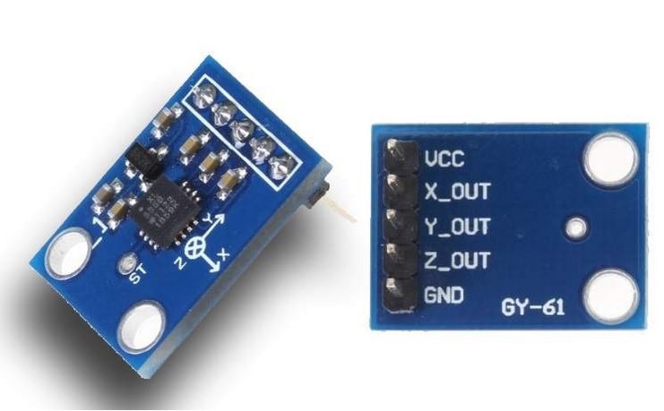
El ADXL335 mide la aceleración en los ejes X, Y y Z y proporciona una salida de tensión analógica proporcional a la aceleración en estos 3 ejes.
Los microcontroladores pueden procesar estos voltajes convirtiéndolos en señales digitales utilizando ADC.
En el tutorial de hoy hemos decidido probar el Acelerómetro ADXL345. Para ello hemos usado:
- Un Arduino UNO.
- Cables.
- Protoboard, opcional
- Acelerómetro ADXL345
- 3 Leds, opcional
- 3 Resistencias.
Ejemplo
Encontrar el balanceo y la inclinación del dispositivo usando voltajes analógicos del módulo de acelerómetro y mostrarlos en el monitor serial de Arduino.
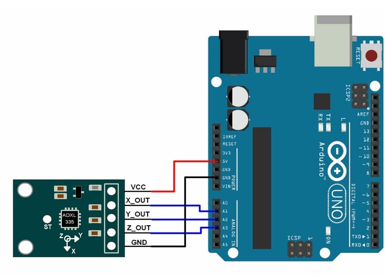
#include const int x_out = A1; /* connect x_out of module to A1 of UNO board */
const int y_out = A2; /* connect y_out of module to A2 of UNO board */
const int z_out = A3; /* connect z_out of module to A3 of UNO board */
void setup() {
Serial.begin(9600);
}
void loop() {
int x_adc_value, y_adc_value, z_adc_value;
double x_g_value, y_g_value, z_g_value;
double roll, pitch, yaw;
x_adc_value = analogRead(x_out); /* Digital value of voltage on x_out pin */
y_adc_value = analogRead(y_out); /* Digital value of voltage on y_out pin */
z_adc_value = analogRead(z_out); /* Digital value of voltage on z_out pin */
Serial.print("x = ");
Serial.print(x_adc_value);
Serial.print("\t\t");
Serial.print("y = ");
Serial.print(y_adc_value);
Serial.print("\t\t");
Serial.print("z = ");
Serial.print(z_adc_value);
Serial.print("\t\t");
//delay(100);
x_g_value = ( ( ( (double)(x_adc_value * 5)/1024) - 1.65 ) / 0.330 ); /* Acceleration in x-direction in g units */
y_g_value = ( ( ( (double)(y_adc_value * 5)/1024) - 1.65 ) / 0.330 ); /* Acceleration in y-direction in g units */
z_g_value = ( ( ( (double)(z_adc_value * 5)/1024) - 1.80 ) / 0.330 ); /* Acceleration in z-direction in g units */
roll = ( ( (atan2(y_g_value,z_g_value) * 180) / 3.14 ) + 180 ); /* Formula for roll */
pitch = ( ( (atan2(z_g_value,x_g_value) * 180) / 3.14 ) + 180 ); /* Formula for pitch */
//yaw = ( ( (atan2(x_g_value,y_g_value) * 180) / 3.14 ) + 180 ); /* Formula for yaw */
/* Not possible to measure yaw using accelerometer. Gyroscope must be used if yaw is also required */
Serial.print("Roll = ");
Serial.print(roll);
Serial.print("\t");
Serial.print("Pitch = ");
Serial.print(pitch);
Serial.print("\n\n");
delay(1000);
}
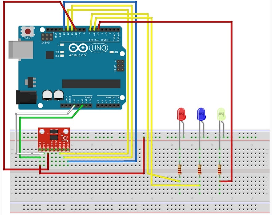
Otra opción sería que la medición se viera reflejada en los Leds, respecto a los LEDs. Queremos usarlos para que nos indique qué ejes están activos.
//Añadimos la librería SPI para conectar con el sensor AXDL 345.
#include
//Asignamos el pin 10 al puerto "Chip Select".
int CS=10;
//ADXL345 registramos las direcciones del sensor en hexadecimal.
#define DEVID 0x00 //Registro del ID del dispositivo.
#define THRESH_TAP 0x1D //Tap Threshold
#define OFSX 0x1E //X-axis offset
#define OFSY 0x1F //Y-axis offset
#define OFSZ 0x20 //Z-axis offset
#define DURATION 0x21 //Tap Duration
#define LATENT 0x22 //Tap latency
#define WINDOW 0x23 //Tap window
#define THRESH_ACT 0x24 //Activity Threshold
#define THRESH_INACT 0x25 //Inactivity Threshold
#define TIME_INACT 0x26 //Tiempo de inactividad
#define ACT_INACT_CTL 0x27 //Axis enable control for...
#define TIME_FF 0x29 //Free-Fall Time
#define TAP_AXES 0x2A //Axis control for tap/double tap
#define ACT_TAP_STATUS 0x2B //Source of tap/double tap
#define BW_RATE 0x2C //Data ratio y modo de ...
#define POWER_CTL 0x2D //Registro del control ...
#define INT_ENABLE 0x2E //Activación del contr....
#define INT_MAP 0x2F //Control del mapeo de ...
#define INT_SOURCE 0x30 //Recurso de interrupciones
#define DATA_FORMAT 0x31 //Control del formato
#define DATAX0 0x32 //X-Axis Data 0
#define DATAX1 0x33 //X-Axis Data 1
#define DATAY0 0x34 //Y-Axis Data 0
#define DATAY1 0x35 //Y-Axis Data 1
#define DATAZ0 0x36 //Z-Axis Data 0
#define DATAZ1 0x37 //Z-Axis Data 1
#define FIFO_CTL 0x38 //FIFO control
#define FIFO_STATUS 0x39 //FIFO estado
//This buffer will hold values read
//from the ADXL345 registers.
char values[10];
char output[20];
//These variables will be used to hold
//the x,y and z axis accelerometer values.
int x,y,z;
double xg, yg, zg;
char tapType=0;
void setup(){
pinMode(7,OUTPUT);//activamos el modo salida de los leds
pinMode(6,OUTPUT);
pinMode(5,OUTPUT);
//Initiate an SPI communication instance.
SPI.begin();
//Configure the SPI connection for the ADXL345.
SPI.setDataMode(SPI_MODE3);
//Create a serial connection to display the
//data on the terminal.
Serial.begin(9600);
//Set up the Chip Select pin to be an
//output from the Arduino.
pinMode(CS, OUTPUT);
//Before communication starts, the
//Chip Select pin needs to be set high.
digitalWrite(CS, HIGH);
//Create an interrupt that will trigger
//when a tap is detected.
attachInterrupt(0, tap, RISING);
//Put the ADXL345 into +/- 4G range
//by writing the value 0x01 to the DATA_FORMAT register.
writeRegister(DATA_FORMAT, 0x01);
//Send the Tap and Double Tap Interrupts to INT1 pin
writeRegister(INT_MAP, 0x9F);
//Look for taps on the Z axis only.
writeRegister(TAP_AXES, 0x01);
//Set the Tap Threshold to 3g
writeRegister(THRESH_TAP, 0x38);
//Set the Tap Duration that must be reached
writeRegister(DURATION, 0x10);
//100ms Latency before the second tap can occur.
writeRegister(LATENT, 0x50);
writeRegister(WINDOW, 0xFF);
//Enable the Single and Double Taps.
writeRegister(INT_ENABLE, 0xE0);
//Put the ADXL345 into Measurement Mode
// by writing 0x08 to the POWER_CTL register.
writeRegister(POWER_CTL, 0x08); //Measurement mode
readRegister(INT_SOURCE, 1, values);
//Clear the interrupts from the INT_SOURCE register.
}
void loop(){
//Reading 6 bytes of data starting at
//register DATAX0 will retrieve the x,y and z
//acceleration values from the ADXL345.
//The results of the read operation will
//get stored to the values[] buffer.
readRegister(DATAX0, 6, values);
//The ADXL345 gives 10-bit acceleration values, but
//they are stored as bytes (8-bits).
//To get the full value, two bytes must be combined for each axis.
//The X value is stored in values[0] and values[1].
x = ((int)values[1]<<8)|(int)values[0];
//The Y value is stored in values[2] and values[3].
y = ((int)values[3]<<8)|(int)values[2];
//The Z value is stored in values[4] and values[5].
z = ((int)values[5]<<8)|(int)values[4]; //COnversión el valor reportado por el acelerómetro por G's. //With 10 bits measuring over a +/-4g range we can //find how to convert by using the equation: // Gs = Measurement Value * (G-range/(2^10)) //or Gs = Measurement Value * (8/1024) xg = x * 0.0078; yg = y * 0.0078; zg = z * 0.0078; if(tapType > 0)
{
if(tapType == 1){
Serial.println("SINGLE");
Serial.print(x);
Serial.print(',');
Serial.print(y);
Serial.print(',');
Serial.println(z);
}
else{
Serial.println("DOUBLE");
Serial.print((float)xg,2);
Serial.print("g,");
Serial.print((float)yg,2);
Serial.print("g,");
Serial.print((float)zg,2);
Serial.println("g");
}
detachInterrupt(0);
delay(500);
attachInterrupt(0, tap, RISING);
int Type=0;
}
if(x<-20){//condición para que reconozca
//el movimiento del eje.
digitalWrite(7,HIGH);
}
else{digitalWrite(7,LOW);}
if(y<-20){ digitalWrite(6,HIGH);} else{digitalWrite(6,LOW);} if(z!=-1){//el sensor cuando está bocaabajo marca -1G digitalWrite(5,HIGH);} else{digitalWrite(5,LOW);} delay(10); } //This function will write a value to a register on the ADXL345. //Parameters: // char registerAddress - The register to write a value to // char value - The value to be written to the specified register. void writeRegister(char registerAddress, char value){ //Set Chip Select pin low to signal the beginning of an SPI packet. digitalWrite(CS, LOW); //Transfer the register address over SPI. SPI.transfer(registerAddress); //Transfer the desired register value over SPI. SPI.transfer(value); //Set the Chip Select pin high to signal the //end of an SPI packet. digitalWrite(CS, HIGH); } //This function will read a certain number of //registers starting from a specified address //and store their values in a buffer. //Parameters: // char registerAddress - The register addresse //to start the read sequence from. // int numBytes - The number of registers that should be read. // char * values - A pointer to a buffer where the //results of the operation should be stored. void readRegister(char registerAddress, int numBytes, char * values){ //Since we're performing a read operation, //the most significant bit of the register address should be set. char address = 0x80 | registerAddress; //If we're doing a multi-byte read, bit 6 needs to be set as well. if(numBytes > 1)address = address | 0x40;
//Set the Chip select pin low to start an SPI packet.
digitalWrite(CS, LOW);
//Transfer the starting register address that needs to be read.
SPI.transfer(address);
//Continue to read registers until we've read
//the number specified, storing the results to the input buffer.
for(int i=0; i<numBytes; i++){
values[i] = SPI.transfer(0x00);
}
//Set the Chips Select pin high to end the SPI packet.
digitalWrite(CS, HIGH);
}
void tap(void){
//Clear the interrupts on the ADXL345
readRegister(INT_SOURCE, 1, values);
if(values[0] & (1<<5))tapType=2;
else tapType=1;;
}